Electronics projects Arduino projects Diy Circuit Diagram
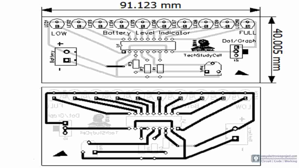
Electronics projects Arduino projects Diy Circuit Diagram Step 3: Circuit Design. The core of this battery level marker circuit is LM3914 IC. This IC takes analog voltage as input and drives 10 LED's directly as per the level of alternating voltage. In this circuit, there is no need for resistors in arrangement with LEDs because the current is directed by the IC itself. The calibration for this Arduino 6 LED battery level indicator circuit must be done carefully, if you did not calibrate correctly, the circuit will show incorrect voltage level of the battery. I will design a circuit for you, if you want me to proceed with your requirements. Regards. Reply. GR says. May 9, 2017 at 12:25 pm. Hi faizan, 1. basically its a battery voltage detector cum indicator circuit. 2. the output from a transformer is 6V, 12V, 24V resp., depending on the supplied input. O/p is A.C. 3. by converting it into D.C. I've to design a circuit which will detect and indicate the voltage o/p by colored LED lamps. Such as, Blue LED - 6V Green LED - 12V Red LED - 24V 4.

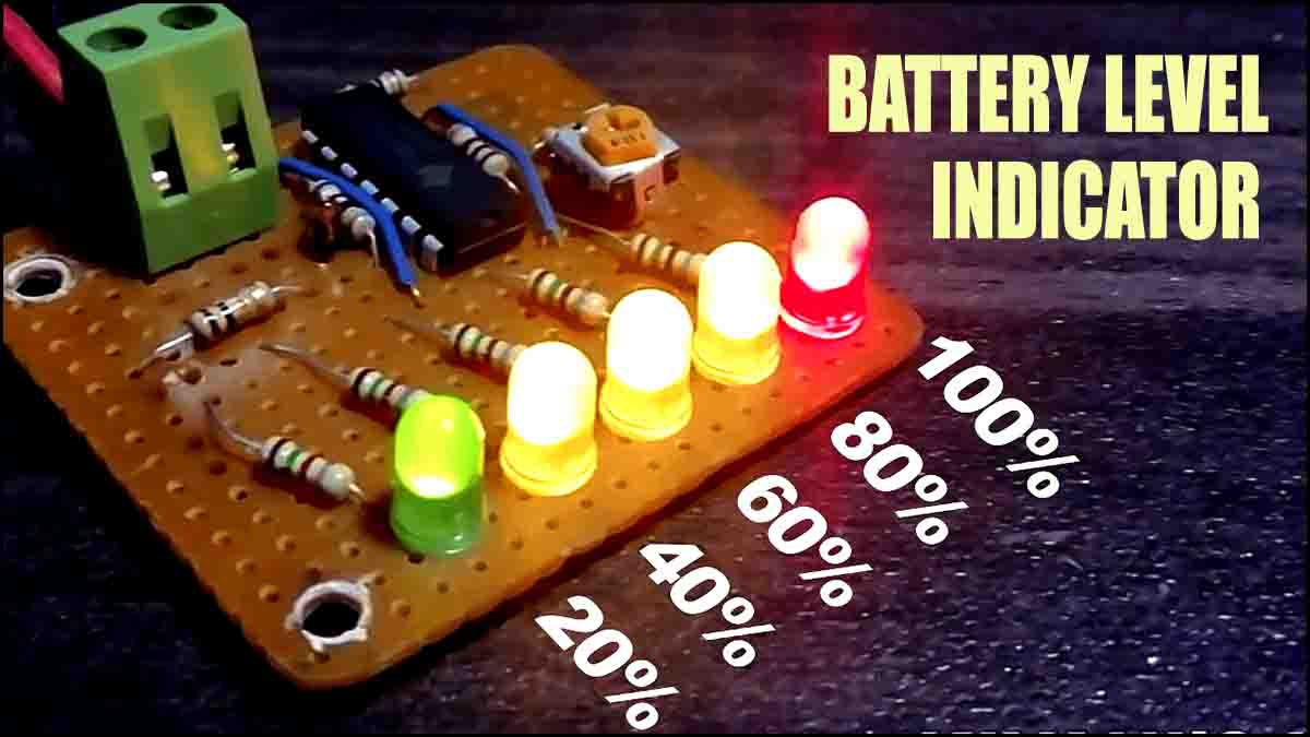
In this project, I will show you how to design a simple Battery Level Indicator Circuit using easily available components. Battery level indicator indicates the status of the battery just by glowing LED's. For example six LED's are glowing means battery capacity 60% remains. This article explains you how design battery level indicator.
How To Design A Battery Level Indicator circuit? Circuit Diagram
Now our battery level indicator circuit is ready.Now match circuit according to the circuit diagram and. Give input power supply to the circuit. NOTE:We can give maximum 15V DC power supply to this circuit. As in picture when I give above 13V DC input then all 5-LEDs is glowing.
Working Principle of the Battery Level Indicator Circuit. The battery level indicator circuit works on the principle of measuring the voltage drop across a series of resistors connected in a voltage divider configuration. This voltage drop is then compared to a reference voltage to determine the battery level. The circuit consists of a battery

Battery Level Indicator Circuit Principle, Design, Diagram Circuit Diagram
In this project I will show you how we can use the classic LM3914 IC to create an LED Battery Level Indicator. Along the way I will show you how the IC works and explain why it is not the most precise circuit for a Li-Ion battery pack. And at the end I will show you how I created my own, more precise Battery Level Indicator circuit with a
